


A Voltage Regulator IC is an essential electronic component designed to maintain a stable output voltage regardless of variations in input voltage, load conditions, or temperature changes. These ICs ensure reliable power delivery to electronic circuits by preventing fluctuations that could damage sensitive components.
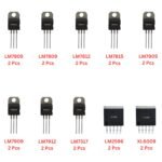
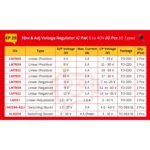
This 20-piece Positive Voltage Regulator Assortment includes a mix of linear and switching regulators designed for a variety of DC power regulation needs. The set consists of fixed-voltage regulators (LM78XX and LM79XX series), an adjustable linear regulator (LM317), and switching regulators (LM2596-ADJ and XL6009).
IC Pin Configuration:
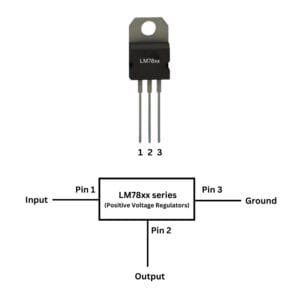
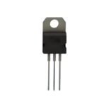
For these regulators, the pinout is generally the same across the LM78xx series, with 3 pins:
- Pin 1: Input (IN)
This pin is for the input voltage. The voltage applied here should be higher than the output voltage (by at least 2V), usually a DC voltage. - Pin 2: Ground (GND)
This is the common ground for both input and output. Connect the negative terminal of your power supply to this pin. - Pin 3: Output (OUT)
This pin provides the regulated output voltage. For LM7805, this will be 5V; for LM7812, it will be 12V, etc.
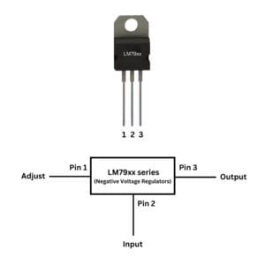
The LM79xx series has a similar pinout to the LM78xx, but for negative output voltages.
- Pin 1: Input (IN)
This pin is for the negative input voltage. It should be lower than the output voltage, typically -V DC. - Pin 2: Ground (GND)
This is the ground pin, also referred to as the common reference point. - Pin 3: Output (OUT)
This pin provides the regulated negative output voltage. For LM7905, it will be -5V; for LM7912, it will be -12V, etc.
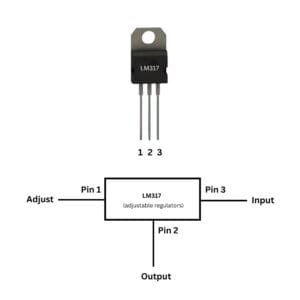
The LM317 has 3 pins and is adjustable:
- Pin 1: Adjust (ADJ)
This is the adjustment pin. You set the output voltage by using a resistor divider (typically a potentiometer and a fixed resistor) between the output and this pin. - Pin 2: Output (OUT)
This pin provides the regulated output voltage. The output voltage is determined by the resistor values connected between the adjust pin and ground. - Pin 3: Input (IN)
This is the input voltage pin, where you connect a voltage source higher than the desired output voltage.
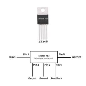
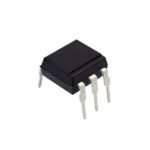
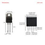
The LM2596-ADJ is a switching regulator, and it has 5 pins:
- Pin 1: Input (IN)
This pin is for the input voltage (higher than the output voltage). The voltage should typically be between 4V to 40V DC. - Pin 2: Ground (GND)
This is the common ground pin for the entire circuit. - Pin 3: Output (OUT)
This is where the regulated, step-down output voltage is available. You set the output voltage using the adjustment pin (Pin 4). - Pin 4: Feedback (FB)
This is the feedback pin. It is used to adjust the output voltage. You connect a resistor divider from the output to this pin to set the desired output voltage. - Pin 5: On/Off (EN)
This pin is used to enable or disable the regulator. Typically, it is connected to high voltage (e.g., 5V or 12V) to enable the output. If grounded, the output is disabled.
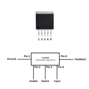
The XL6009 is a boost converter with 5 pins:
- Pin 1: Input (IN)
This pin is where you connect the input voltage (which should be lower than the desired output voltage). It typically ranges from 5V to 32V DC. - Pin 2: Ground (GND)
This is the common ground pin. - Pin 3: Output (OUT)
This is the pin where the boosted output voltage is available. The output voltage is determined by the feedback pin. - Pin 4: Feedback (FB)
The feedback pin helps regulate the output voltage. You adjust it using a resistor divider between the output and this pin. - Pin 5: Enable (EN)
This is the enable pin. It turns the regulator on or off. When connected to high voltage, the regulator is active.
Reviews
Clear filtersThere are no reviews yet.